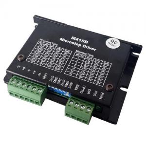
Analog Input Stepper Driver
POT or Joystick speed controllable stepper driver
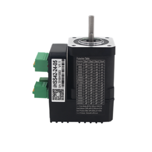
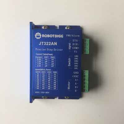
JT322AN is analog input stepper motor driver, which can be driven by an external potentiometer or driver. Using the latest 32 DSP technology, providing precision 0.05A current setting unit , and taking advanced digital filtering techniques, anti-resonance technology and precision current control technology to make it implement precise smooth operation, extra low noise . It’s widely used in semiconductor, electronic processing equipment, medical and precision equipment.
Capable of driving Nema11, Nema14, Nema17 and Nema23 series of two-phase hybrid stepper motors.
User Manual of JT322AN
Control Mode: switch control
Max Input Frequency: 200KHz
Input Voltage Range: 12-30VDC
Suggested Power Supply Voltage Range: 12-24 VDC
Output Current: 0.50 - 2.00 A
Software Configuration. Resolution Range: 200 - 102,400
DIP Switch Resolution Setings: 200,400, 800, 1600, 3200, 6400, 12800, 25600
Software Cofig Current Range: 0.50 - 2.20A
DIP Switch Current Configurations: 0.5A, 0.7A, 1.0A, 1.3A, 1.6A, 1.9A, 2.2A
Logic Current Range: 7-16mA (10mA typical)
Logic Voltage Range: 4-5 VDC for pulse active high (default) , or 0-0.5V for pulse active low
Pulse enabled at: Rising edge
Idle Current Percentage: 50 %
Software Config. Idle Current Percentage: 0-100%
Step Width: 2,500 ns
Minimal Direction Setup Time: 5,000 ns
Protection: Over-current, over-voltage, and stall, phase-error
Isolation Resistance: 500M Ohm
Environment: Avoid dust, oil fog and corrosive gases
Ambient Temperature: 0-50°C
Humidity: 40–95% RH
Operating Temperature: 0-70°C
Vibration: 5.9 m/s2 Max
Storage Temperature: -20-65°C
Control signal connection diagram
(If the controller sends the control signal is +12 ~ +24 V, the PUL-, DIR-, ENA- signal line to increase the 1 / 4W 1K ~ 2K resistor current limit)
Connector description
Typical application wiring diagram
(notice:potentiometer no need to connect power supply, only to connect two pin)
1)Power motor connector CN1
Connector Name Function
6 GND DC Power ground
5 +VDC DC Power anode, can connect during +12V—+24V,users should make sure working voltage not over 30VDC
4 A+ Motor A+
3 A- Motor A-
2 B+ Motor B+
1 B- Motor B-
2)Control signal connect CN2
Connector Name Function
4 Vi Analog signal input, maximum 3.3V, connect potentiometer wiper, not recommend to connect power
3 COM+ Input terminal of control signal public power, can connect +24 voltage
2 DIR- Direction signal: logic “low” threshold direction signal is active
1 STA- Switch-controlled signal: motor runs when logic “low” threshold
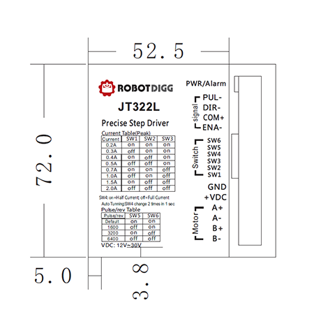
New arrival: Normal Pulse and Direction Stepper Driver JT322 which is similar to DM422 stepper driver from Leadshine.
JT322L 0.1A resolution 0.2A to 0.7A current per phase for NEMA8 or NEMA11 stepper motors 6400 pulse per revolution.