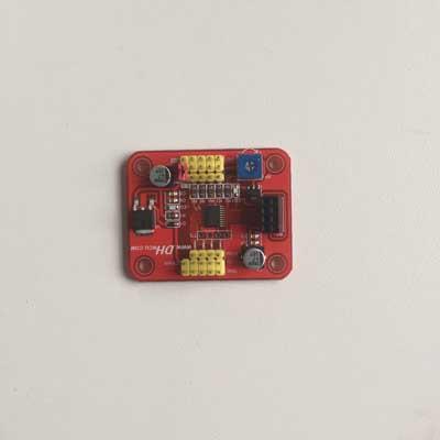
4-channel PWM controller for rc servos

Power supply: 5-7.4VDC
Current: 1A per servo at most
1. Why the servo is jigging?
A 1-1: This section is part of the controller pulse width (angle) of adjustable servo controller, the maximum pulse width can reach 0.5-2.5MS, while the market in general by 90 degrees or 180 degrees steering servo due to mechanical structural constraints, can only reach 120 degrees or 200 degrees, the pulse width of their actual needs, perhaps as long as 1-2MS, so if it is in the limit steering angle jitter, adjust the blue knob counter-clockwise on the board, the pulse width adjusted to the appropriate output.
A 1-2: Another reason is the lack of power steering jitter current or voltage, wide supply voltage controller of this paragraph may be 5-7.4V supply voltage so as not lower than 5V, then that is current, must ensure a servo 1A is a current, do not use battery-powered, battery current is very small, is not moving with the steering gear, which means that if you want to connect up to four servos, please be sure that the power supply current of a sufficient amount of 4A.
2. You can control the high-voltage servo controller servo it? 12V or 24V can control the steering gear it?
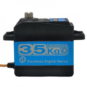
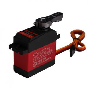
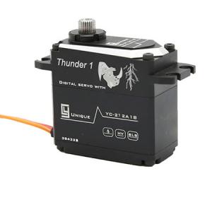
A 2-1: This section controls the high voltage servo servo controller can control 12V or 24V servo. Our company also sells high pressure steering gear. First, let's explain what is high-pressure steering gear, power steering market average are basically 4.8-7.4V, the high voltage supply in general servos 12V-24V, ordinary servos are three lines, high voltage servos are generally 5 lines, three signal lines, two power supply lines, wiring is very simple, as long as the signal line plugged into our control panel in accordance with the ordinary steering gear, then to a large servo powered 12V or 24V power line to so it does not give us the power steering gear control panel again, and generally such a large servo signal line over there 5V output, the output will be able to give us a 5V power supply controller.
3. Why is the time of wireless communication using LED1 flashing, LED lit?
A: 3-1: LED1 is designed for wireless communication when a radio signal indicating whether communication with the normal, the normal time when the wireless communications, LED1 flashes, if LED1 does not blink, that there is no communication on, is not plugged when a wireless module, LED1 is not bright; and the LED indicator light is the power indicator, LED lit indicates normal supply.
4. accidentally reversed the positive and negative power supply, it will burn circuit boards? Servos will burn it?
A 4-1: reverse power does not burn circuit boards, circuit board comes with reverse polarity protection.
A 4-2: reverse power though not burn circuit boards, but if you plug the servo on the circuit board, reverse power, it will burn the steering gear, reverse polarity protection circuit board only protects nothing, steering is direct supply past, reverse the servos will burn.
5. The circuit board may not receive potentiometer, directly in the AD port input voltage signal 0-5V it?
A 5-1: You can not receive potentiometer, 0-5V voltage directly to the input signal, but we must note that the only input 0-5V analog voltage signal can not be input 0-5V digital signal (square wave signal).
A 5-2: Only the power supply to the control board 6V or more, to input 0-5V analog voltage
