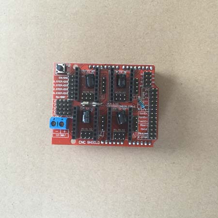
Ardunio cnc shield v3 Breakout Board for CNC Router or 3D printers.
It's used to work with Arduino Uno to control 4 stepsticks. The stepstick is Not included, need to buy separately.
The breakout board can be used for engraving machine, 3D printer driver extension plate, a total of four stepper motor driver module slot. (note Moto Sako does not contain the a4988 stepper motor driver module, need to be in the store to purchase another) can be driven by the 4 road into the motor, and each step electric machine only need two IO mouth. That is to say, six IO mouth can be a very good management, the three step stepper motor, use very convenient, bid farewell to the traditional stepper motor operation is complicated.
Stepper motor control pin, the pin is in the engraving machine, or 3D printer is used, here we make detailed, IO corresponding pictured above.
UNO or Arduino breakout board
8 (EN stepper motor drive enable, active low)
7 and Z.DIR (Z axis direction)
6 and Y.DIR (Y axis direction)
5 and X.DIR (X axis direction)
4 conducting Z.STEP (Z axis stepping control)
3 conducting Y.STEP (Y axis stepping control)
2 conducting X.STEP (X axis stepping control)
"Here is a simple stepper motor control program,
#define EN / / 8 stepping motor enable, active low
Direction control of X_DIR #define 5 //X axis stepper motor
Direction control of Y_DIR #define 6 //y axis stepper motor
Direction control of Z_DIR #define 7 //z axis stepper motor
X_STP #define 2 //x axis stepper control
Y_STP #define 3 //y axis stepper control
Z_STP #define 4 //z axis stepper control
*
/ / function: step function: stepper motor control direction, the number of steps.
/ / parameters: control the direction of dir, dirPin corresponding stepper motor dir pin, stepperPin
corresponding stepper motor step pin, steps step by step number
/ / no return value
* /
Step void (DIR Boolean, dirPin byte, stepperPin byte, int, steps)
{
DigitalWrite (dirPin, dir);
Delay (50);
For (I int = 0; I < i++; steps) {
DigitalWrite (stepperPin, HIGH);
DelayMicroseconds (800);
DigitalWrite (stepperPin, LOW);
DelayMicroseconds (800);
}
}
Void (setup) {// stepper motor will be used in the IO pin is set to output
PinMode (X_DIR, OUTPUT); pinMode (X_STP, OUTPUT);
PinMode (Y_DIR, OUTPUT); pinMode (Y_STP, OUTPUT);
PinMode (Z_DIR, OUTPUT); pinMode (Z_STP, OUTPUT);
PinMode (EN, OUTPUT);
DigitalWrite (EN, LOW);
}
Loop void () {
Step (false, X_DIR, X_STP, 200); //X axis motor reverse 1 turn, 200 step for a circle
Step (false, Y_DIR, Y_STP, 200); //y axis motor reverse 1 turn, 200 step for a circle
Step (false, Z_DIR, Z_STP, 200); //z axis motor reverse 1 turn, 2
00 step for a circle
Delay (1000);
Step (true, X_DIR, X_STP, 200); //X shaft motor is turning 1 turn, 200 step for a circle
Step (true, Y_DIR, Y_STP, 200); //y shaft motor is turning 1 turn, 200 step for a circle
Step (true, Z_DIR, Z_STP, 200); //z shaft motor is turning 1 turn, 200 step for a circle
Delay (1000);
}
The experimental phenomena: stepper motor reversal in a circle, and then pause a second, being a circle, so the cycle.
It is worth noting that: in the plug A4988 module when the attention should not be inserted in the back, stepper motor wiring is:
2B, 1A for a group (red, green), 1B, 2A for a group (blue, yellow) would like to change direction, change the location of one group can be, such as 2B, and 2A exchange.