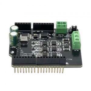
CAN FD Analyzer
Debugger or Analyzer, USB Type c to RS485 serial port and TTL, and Typec to CAN or CANFD
N/CAN-FD bus communication interface card, and CAN/CAN-FD protocol data analyzer. It can be connected to the PC or industrial control host via a USB port to realize transceiver control, data analysis, collection and monitoring of CAN/CAN FD bus network. It is compact and easy to use, which can be used for learning and debugging of CAN/CAN FD bus, and for secondary development and integration into various industrial, power communication, and intelligent control applications that require CAN/CAN FD bus communication.

When using a computer to control the hollow servo motor. it is necessary to have this adapter or analyzer.
This analyzer has two channels, one for USB to CAN, and the other for USB to 485 or TTL, Each channel needs to be wired separately.
When using this debugger under Windows, it requires Wins10 or above. There is no actual test data for other versions of Windows, including Linux-based systems.
Under Windows. USB to CAN does not require a driver, while USB to 485 or TTL requires driver installation.
There are jumper caps labeled i and l on the board, and both are in a connected state.
The function of the jumper cap is to determine whether the 120-ahn terminal resistor is connected.
The function of the jumper cap is to switch between USB to 485 and USB to TTL.
When jumper cap I is connected, it is for USB to 485, when it is disconnected, it is for USB to TTL.
To change the status of the jumper caps, the housing needs to be opened for the switch.


